Network Access Configuration
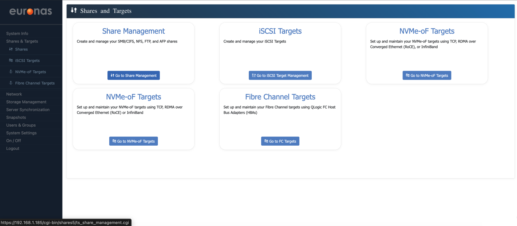
This section covers how storage is presented to clients and how access is configured via the GUI. This includes setting up file-based access such as SMB, along with block-based access using iSCSI and NVMe over TCP, with portal IPs defining the network paths used for storage traffic.
These examples are intended as a guide. Exact configurations will vary depending on the environment, workload requirements, and network design.
During the base installation, the management interface was configured. While this can be used for access, it is not recommended. In this section, we will configure dedicated access networks for file and block services via the GUI.
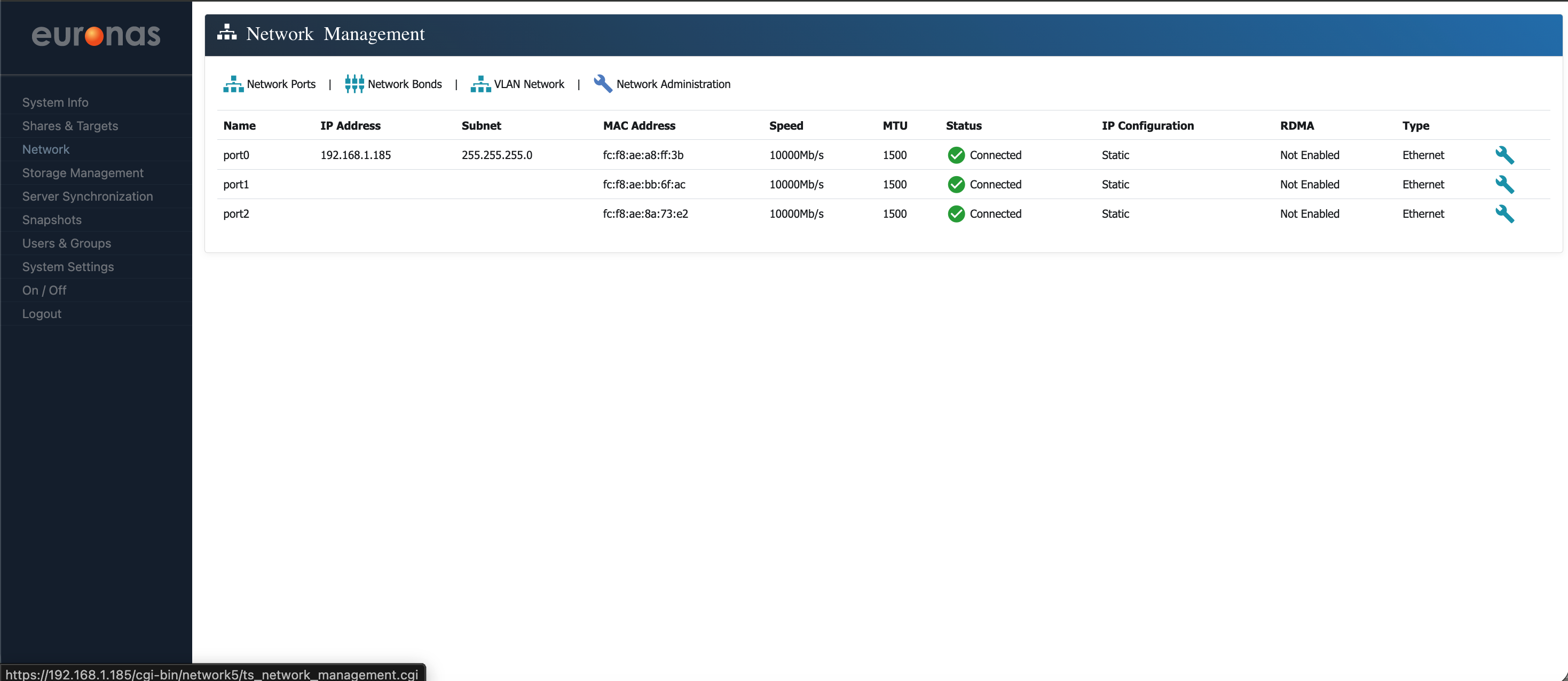
This is where you get a full view of how the networking is configured on the system. You will see all physical interfaces (Network Ports), along with any bonded links and virtual networking components such as VLANs and the internal switching layer. Each interface shows its current state, including IP address, subnet mask, link speed, MTU, and whether it is up and active.
A Network bonds link is a way of combining multiple physical network interfaces into a single logical interface sometimes referred to a LAG or MLAG. This is typically done to provide additional bandwidth, resilience, or both, depending on how it is configured. If one link fails, the other can continue to carry traffic, or both can be used together to increase throughput.
The system includes an internal switching layer that controls how network interfaces, VLANs, and services are connected. This allows you to define how traffic flows within the system in a structured way, rather than relying purely on the physical network layout.
In practice, this functions in a similar way to a virtual switch, allowing you to map front-end client access and back-end storage traffic to specific interfaces or networks. These networks can be physical or defined virtually within the server, providing flexibility in how traffic is segmented and managed. This allows for clear separation of traffic types, improved control over how services are exposed, and alignment with the performance and resilience requirements of the workload.
In this example, we are working with direct network connections. These will be configured in the same way as the management interface configured earlier, so the process should be familiar. The intention is to bring each interface online in a controlled and predictable way, rather than relying on any default behaviour.
From this screen, you can review the current configuration, confirm that interfaces are up and reachable, and make any required changes. This is also where you would return if you needed to troubleshoot connectivity or adjust the network layout as the deployment evolves.
As shown, the management interface configured earlier is present, along with two additional interfaces that do not currently have IP addresses assigned. While the management interface can be used for general access, this is not recommended. It is best practice to separate management traffic from storage and client access traffic.
In this example, we will first configure an interface for file-based access, which will be used for SMB connectivity. Once this is in place, we will move on to configuring portal IPs for block-based services such as iSCSI and NVMe over TCP.
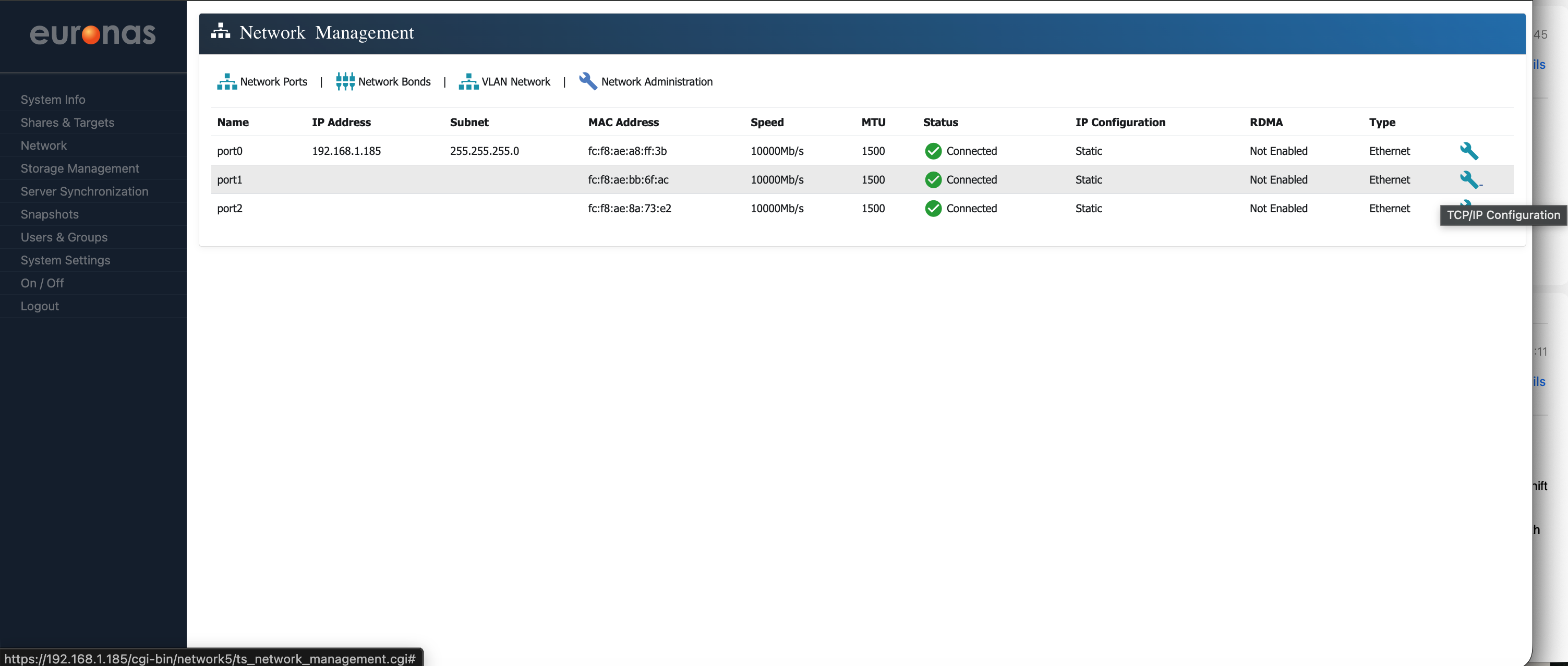
We will now assign an IP address to port1.
Select the spanner icon to the right of port1 to open the configuration screen.
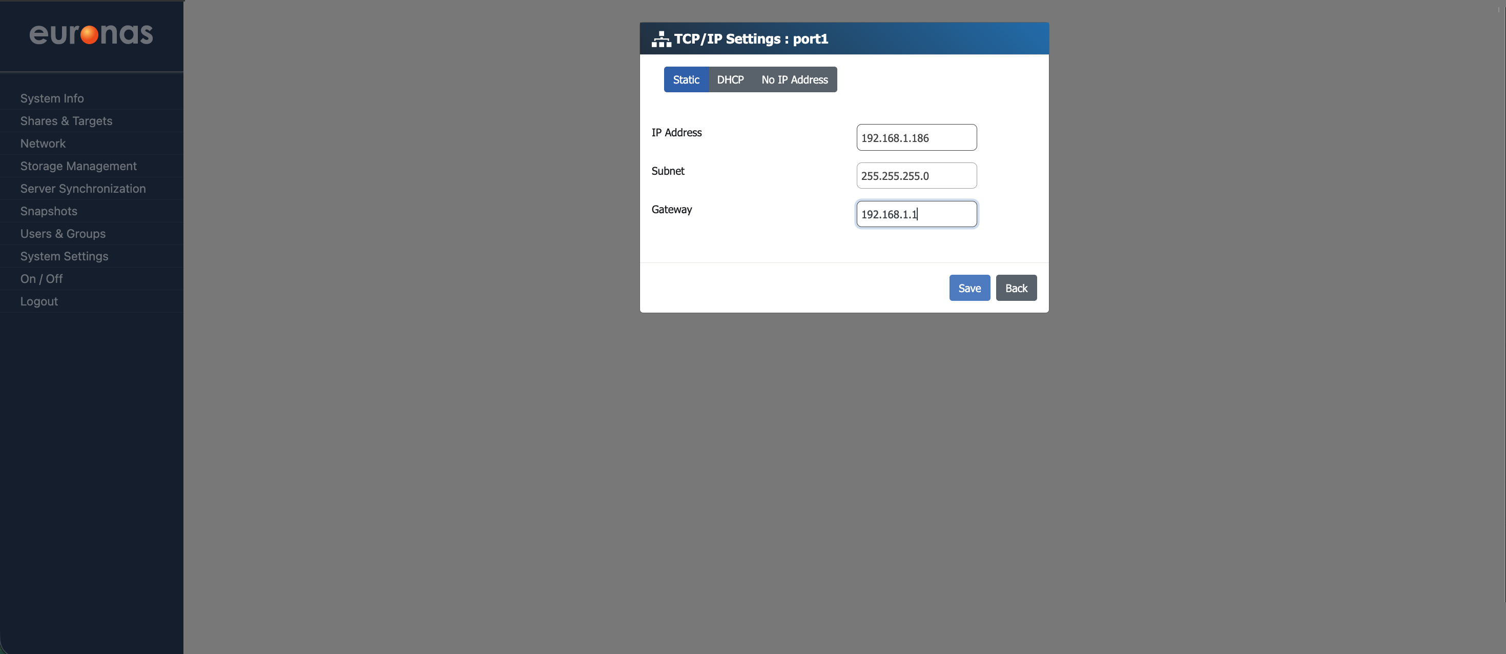
On the TCP/IP Settings page, you can define the IP address, subnet mask, and default gateway for the selected interface. The screen will also clearly show which port is being configured. You also have the option to use DHCP or to leave the IP address blank.
For this example, a static IP address of 192.168.1.186 is used, with a subnet mask of 255.255.255.0 and a default gateway of 192.168.1.1.
These values are specific to this environment. Your network configuration will vary depending on your addressing scheme and network design, so ensure the correct settings are applied for your deployment.
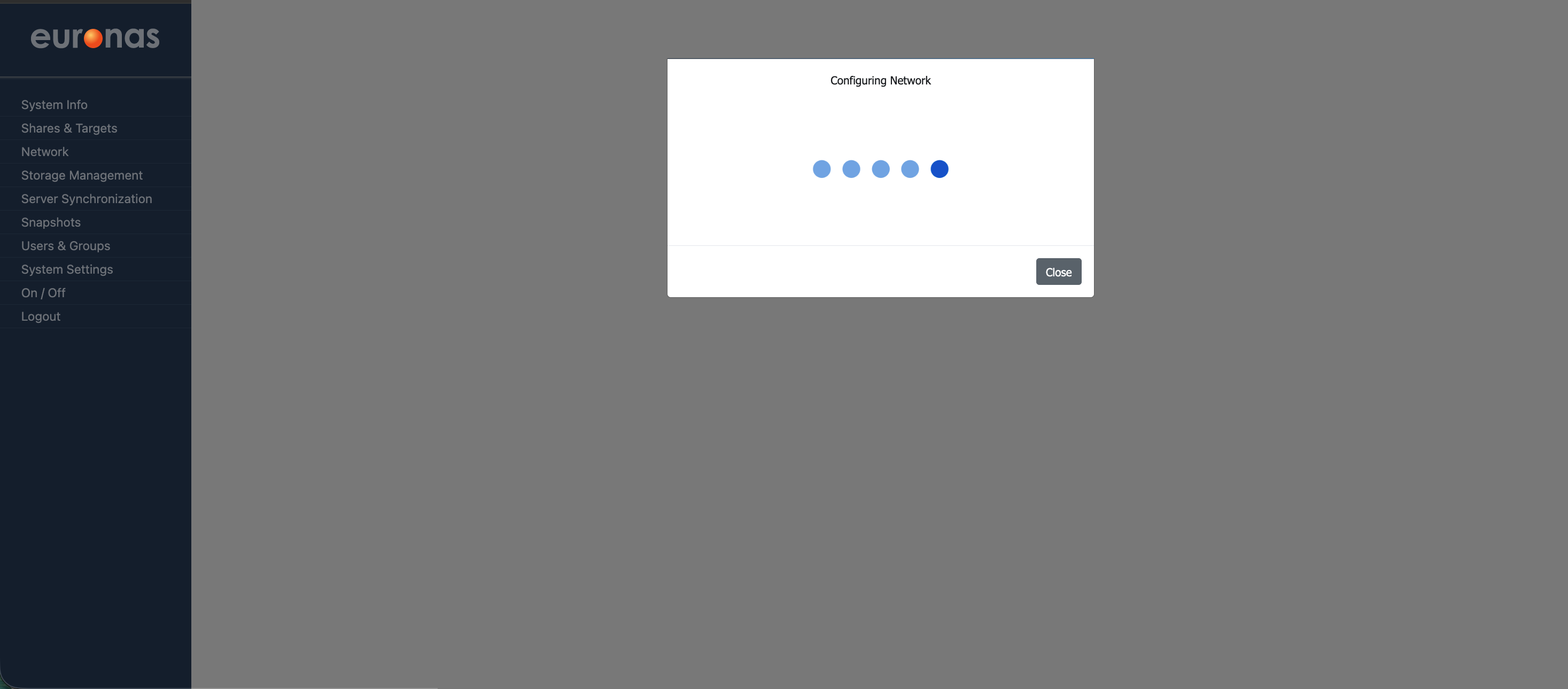
Once you select Save, the system will apply the configuration to the port in real time.
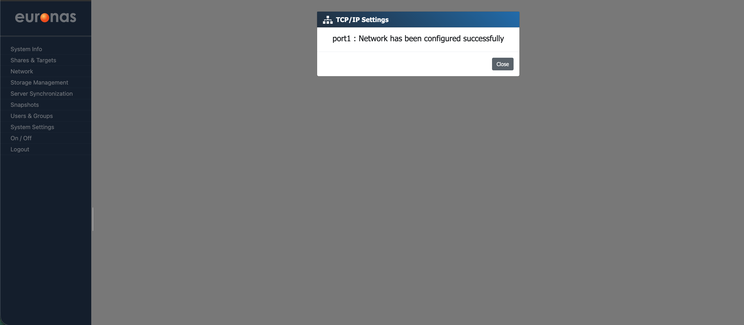
As shown, the system will confirm that the network port (port1) has been configured successfully. Select Close to return to the network management screen.
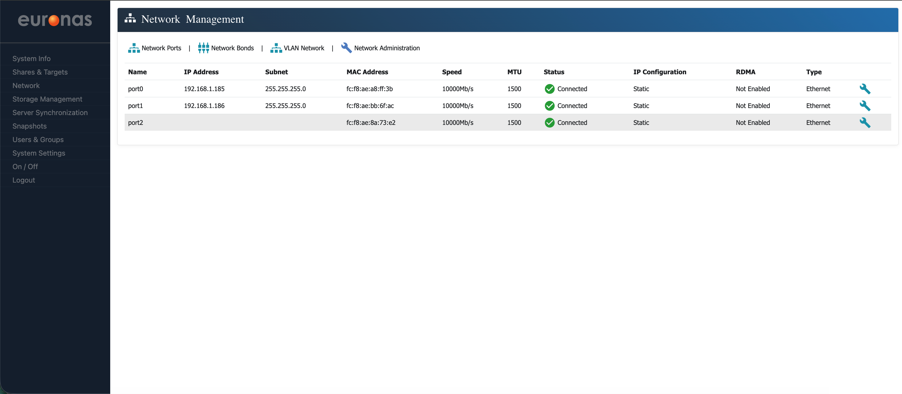
As shown, an access interface has now been successfully configured on port1 with an IP address of 192.168.1.186.
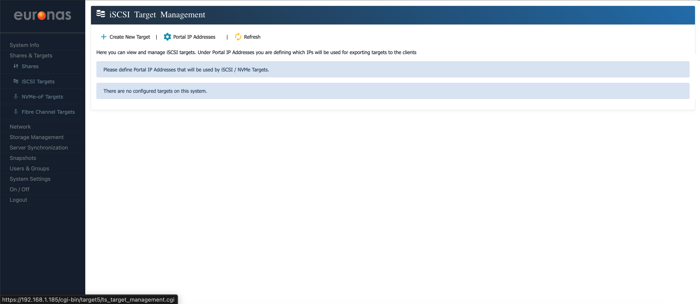
This will open the iSCSI Target Management screen.
Select the gear icon labelled Portal IP Addresses to open the portal IP configuration wizard.
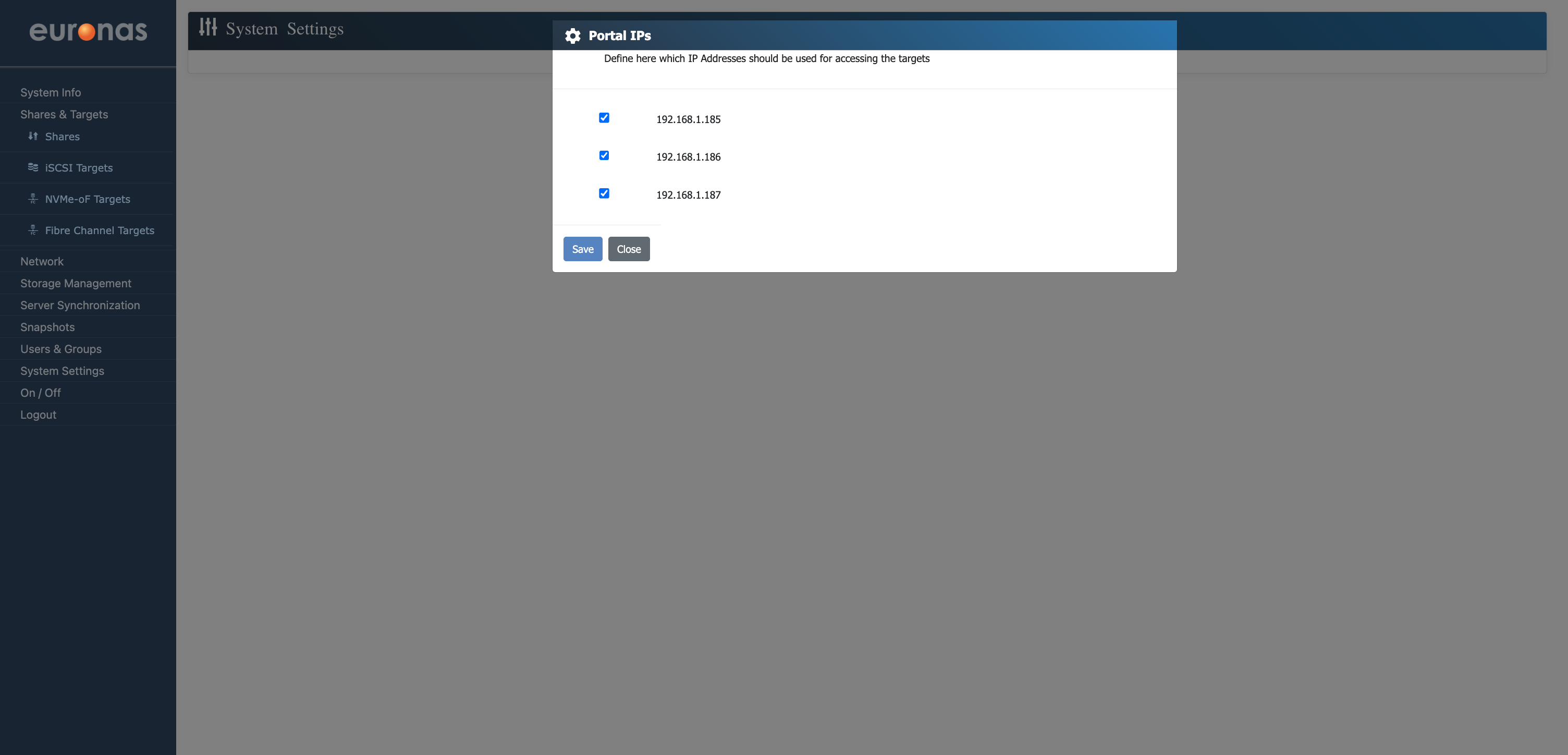
Portal IPs define the IP addresses that clients use to access block storage services such as iSCSI and NVMe over TCP. These act as the entry points for storage traffic into the system.
By selecting the relevant IP addresses, you control which network interfaces and paths are used for client access. This allows you to enable or restrict access to storage services based on your network design and ensures that storage traffic is directed over the intended networks.
Select Save to apply and store the configuration.
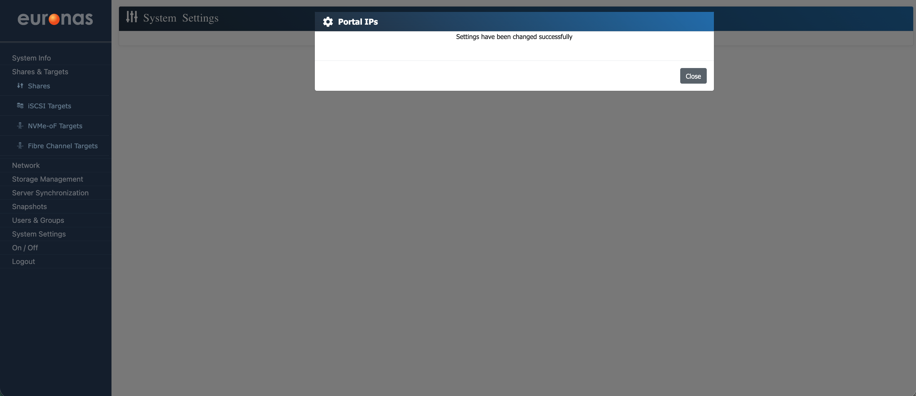
As shown, the system will confirm that the portal IP configuration has been updated successfully.
Select Close to return to the iSCSI Target Management screen.
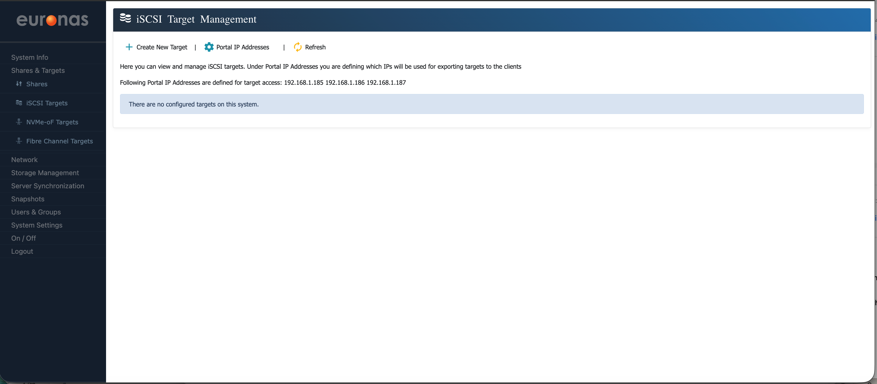
As shown, the selected portal IPs have been successfully configured and are ready for use.