
Pool Creation
As discussed previously, the euroNAS HA Cluster is designed to keep services online in the event of a node failure, using a dedicated cluster control layer that continuously monitors node state and orchestrates failover across the shared storage platform. We will now connect the newly created cluster to the shared storage layer and bring the HA environment online. The platform is flexible in that the shared storage can be presented through multiple methods including dual-controller shared backplane configurations, SAS, or iSCSI. The key requirement is that both nodes maintain visibility of the same shared disk identifiers, allowing the cluster control layer to coordinate clean and deterministic service failover between nodes.
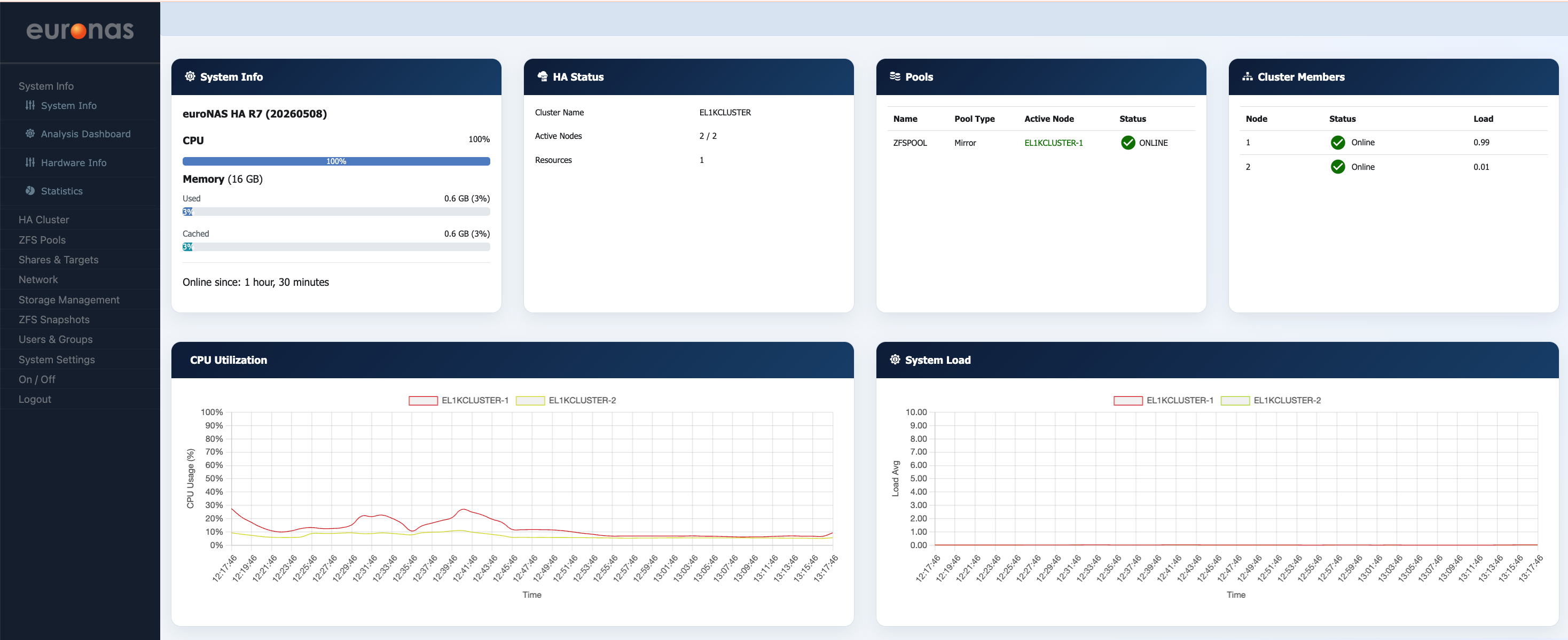
From the System Info page, select the Storage Management option.
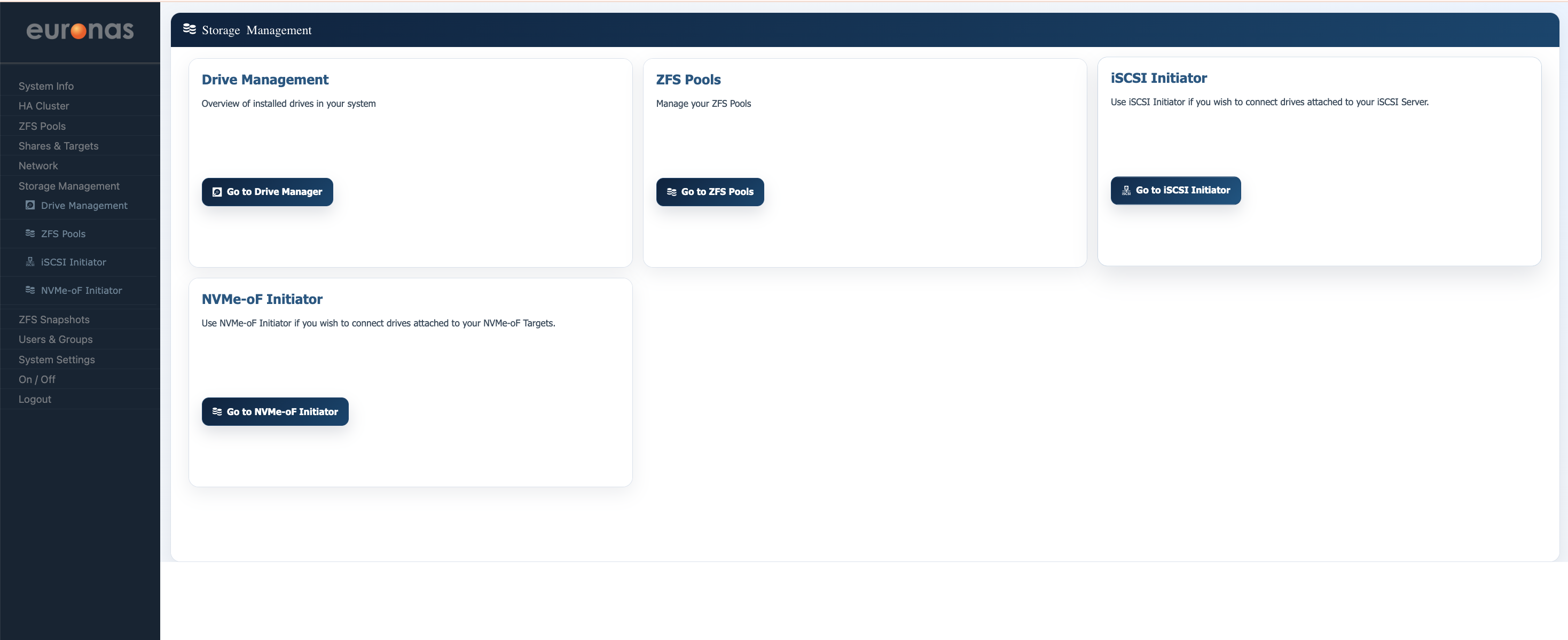
This example will utilise iSCSI as the shared storage platform. However, as discussed previously, this is not the only supported configuration. From the Storage Management page, select the “Go to iSCSI Initiator” option.
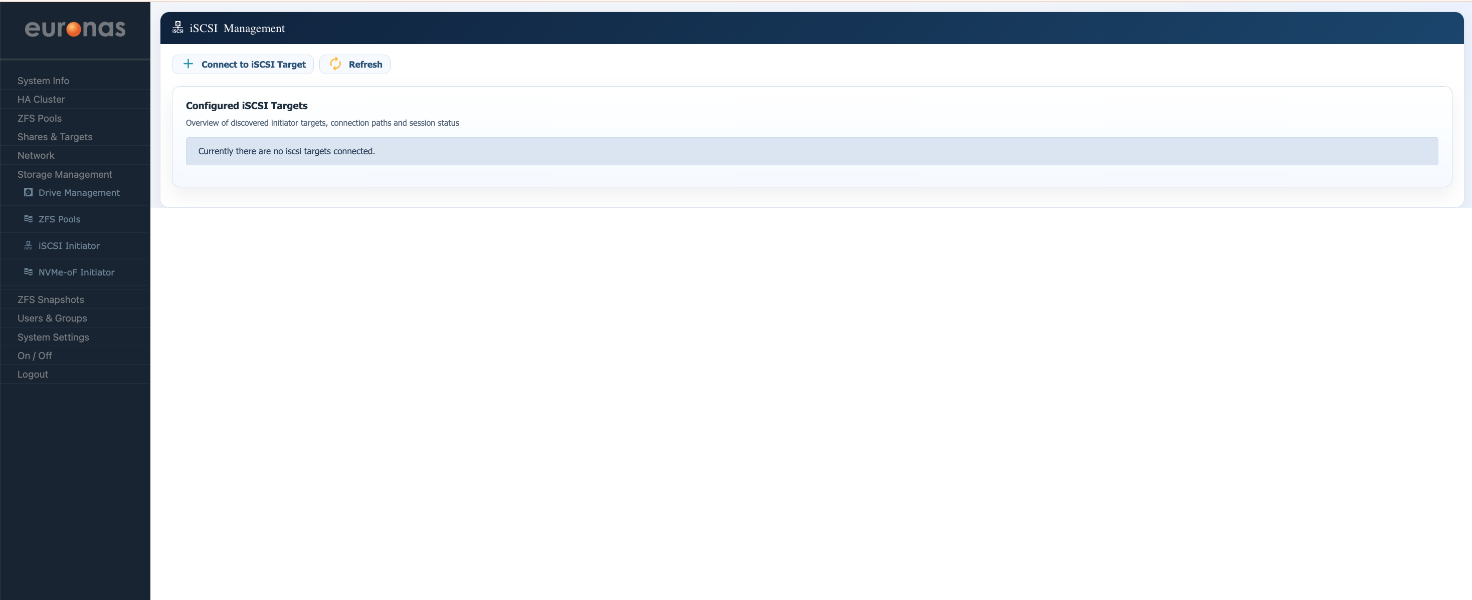
The iSCSI Management page provides a central view of all configured iSCSI storage connections on the node, including discovered targets, active sessions, and available connection paths. At present, no iSCSI targets are connected to the system. To begin attaching the shared storage platform to the cluster node, select the “Connect to iSCSI Target” option.
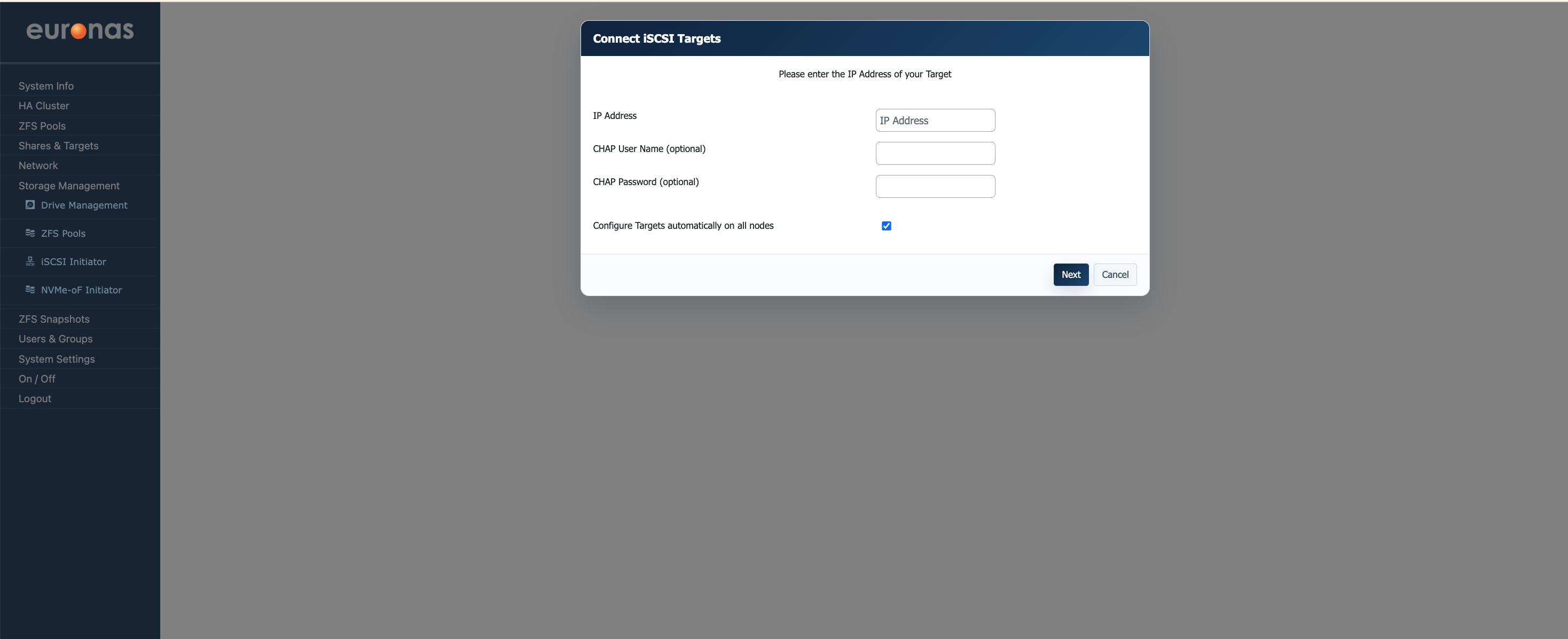
Enter the IP address of the target storage platform that will present the shared iSCSI LUNs to the cluster. If CHAP authentication is configured on the target system, enter the appropriate username and password credentials.
CHAP authentication provides an additional security layer between the initiator and the storage target, helping prevent unauthorised systems from connecting to the shared storage platform. While not mandatory in isolated or dedicated storage networks, it is strongly recommended in environments where the storage network is shared or accessible outside of a tightly controlled backend infrastructure.
When “Configure Targets automatically on all nodes” is enabled, the discovered iSCSI target configuration will be replicated across all cluster nodes automatically, simplifying deployment consistency and reducing manual configuration steps during HA setup. Once complete, select “Next” to continue.
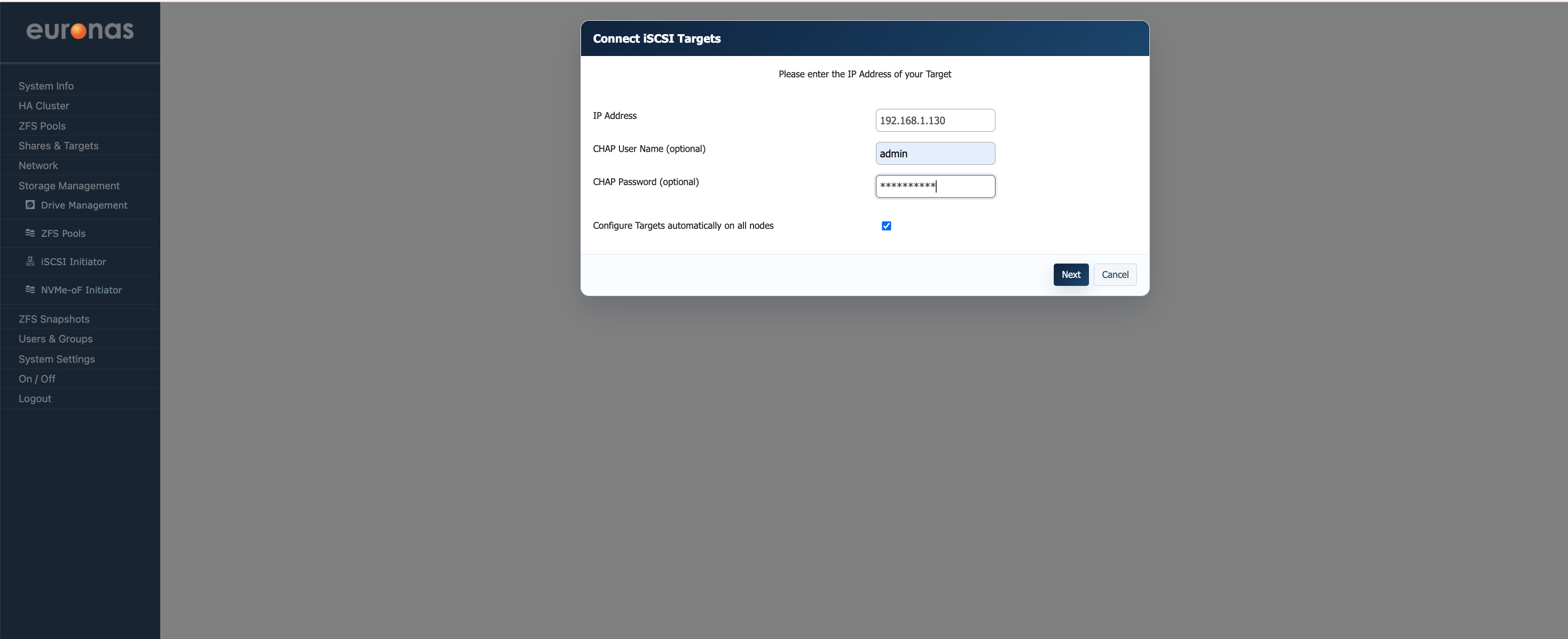
In this example, the IP address of the shared storage platform has been entered along with the CHAP authentication credentials. CHAP helps ensure that only authorised initiators can connect to the shared storage target and is strongly recommended for secured or shared storage networks.
The “Configure Targets automatically on all nodes” option remains enabled, allowing the configuration to be replicated automatically across the cluster nodes. Once complete, select “Next” to continue.
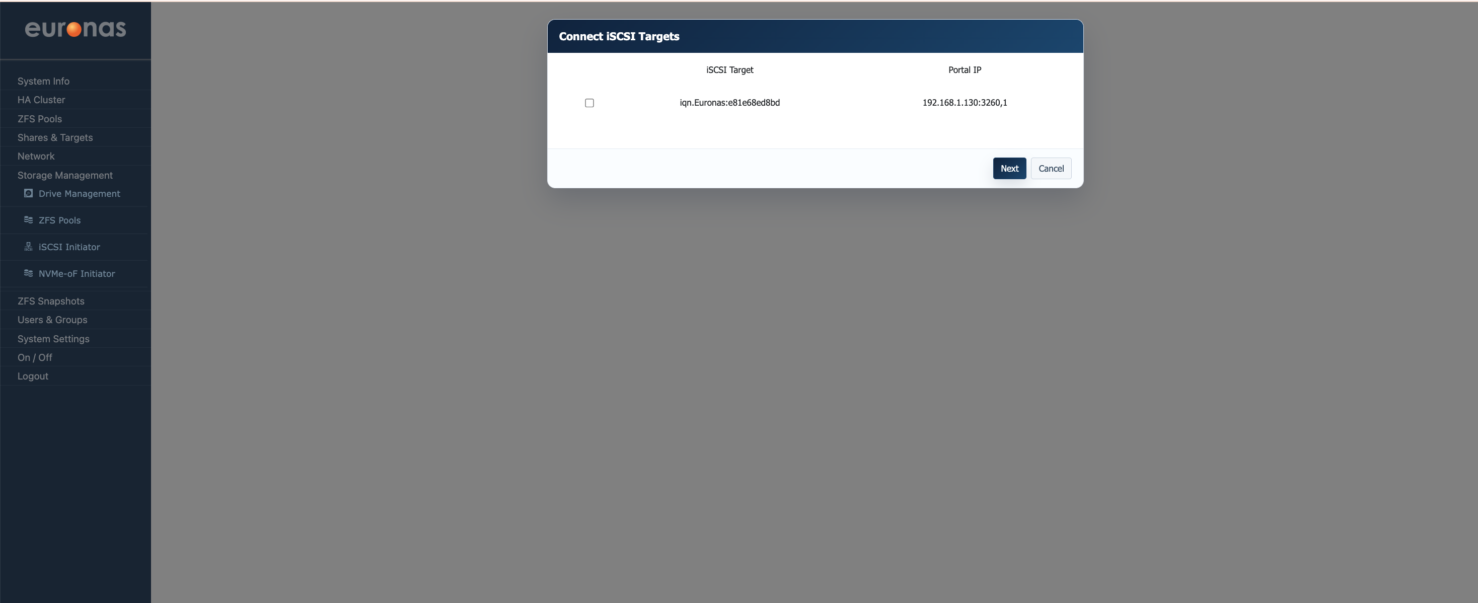
The Connect iSCSI Targets page displays all available iSCSI targets discovered by the system. Each target is identified by its unique IQN (iSCSI Qualified Name) along with the associated portal IP address and port used for connectivity. Where multiple targets or portals are available, ensure the correct storage target is selected before proceeding.
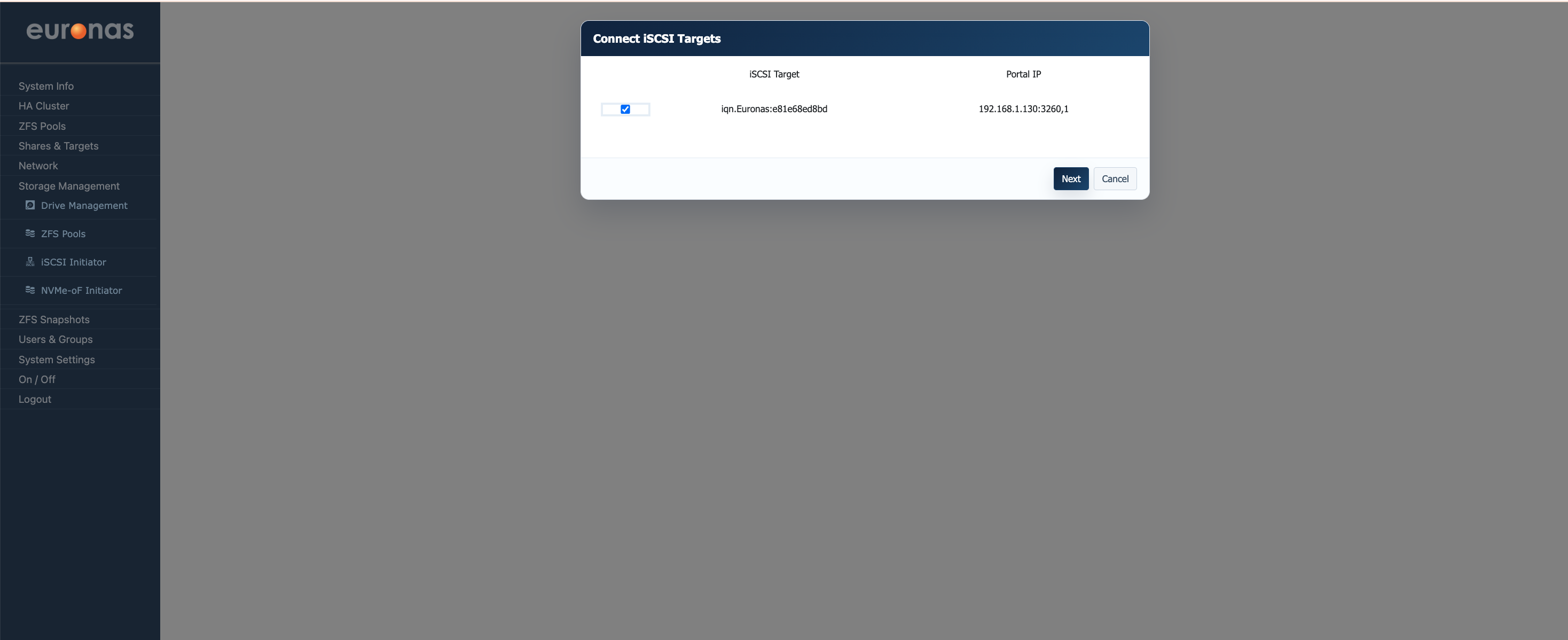
Select the required target from the list and click Next to continue the connection process. In this example the system has discovered the target iqn.Euronas:e81e68ed8bd available on portal 192.168.1.130:3260.
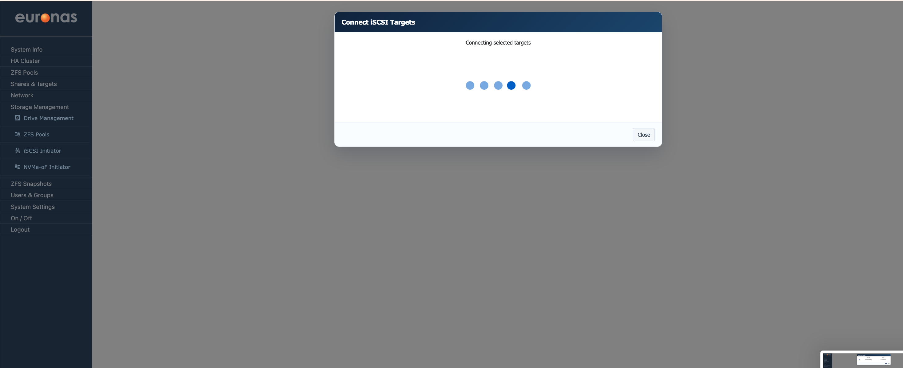
Once the required target has been selected the system will initiate the iSCSI connection process. During this stage euroNAS establishes communication with the remote target, negotiates the session, and validates storage access. Depending on network latency and storage responsiveness this process may take several seconds to complete. Once the connection has been established successfully the presented storage devices will become available to the operating system for pool creation or cluster use.
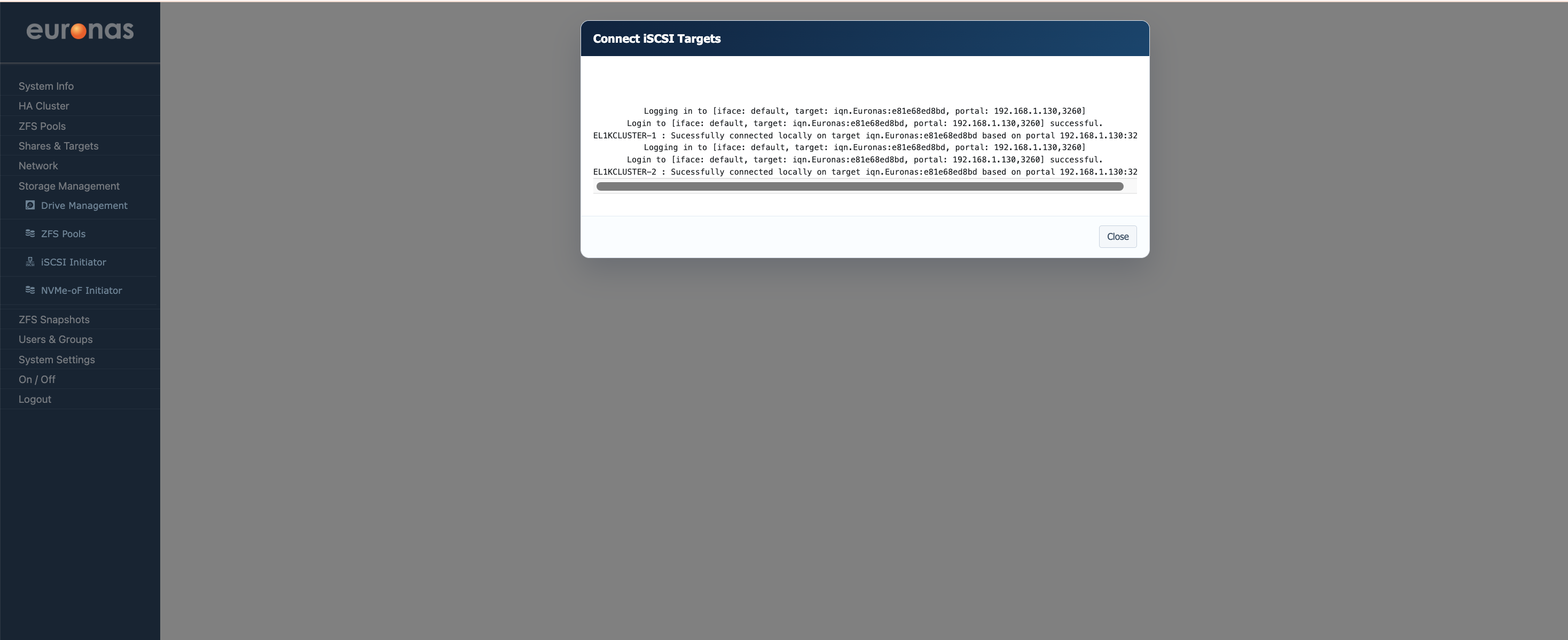
Once the connection process has completed euroNAS will display the connection status for each node. In this example both nodes have successfully established local iSCSI sessions to the shared target.
This confirms that both nodes can see the same shared storage device which is a requirement for HA failover operation. At this stage the shared disks are now available for cluster services, pool creation, or shared storage configuration.
If either node fails to establish access to the shared storage the cluster will prevent ZFS pool creation to avoid an inconsistent or split storage configuration between nodes.
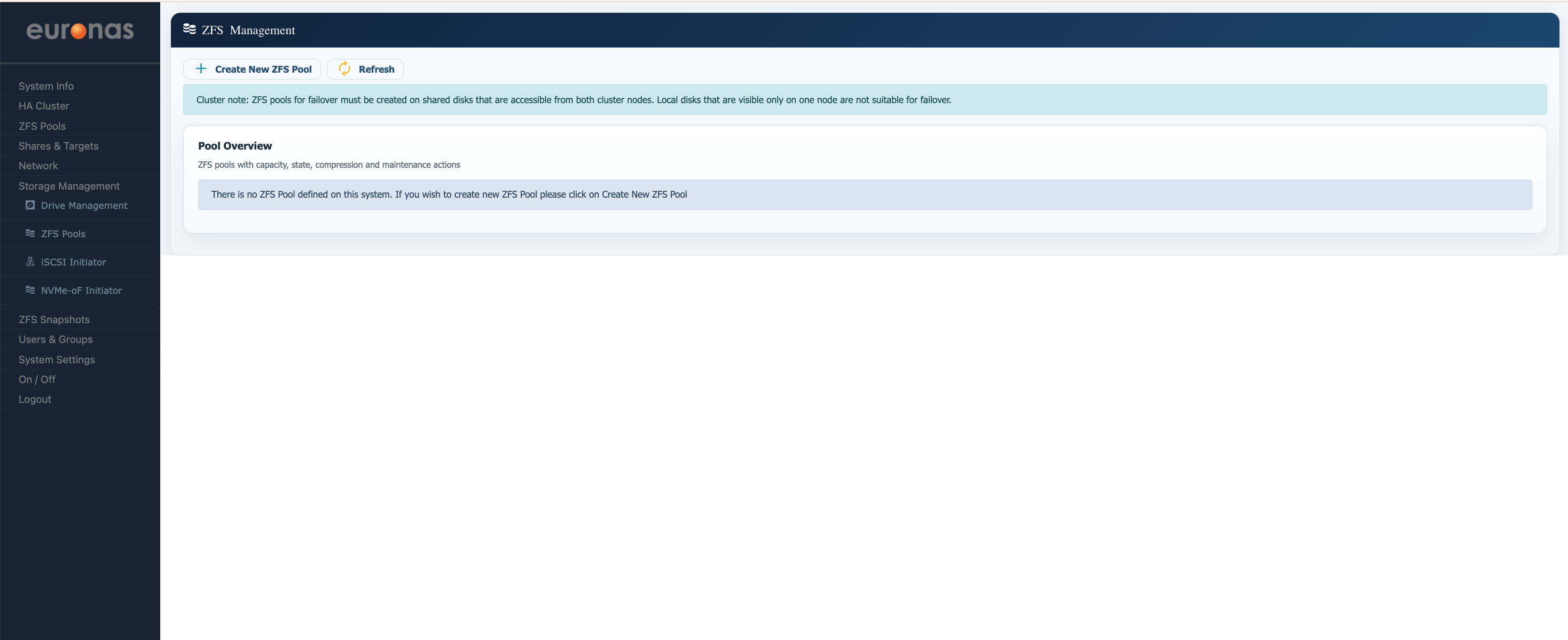
The ZFS Management page provides an overview of all configured storage pools within the system. From this interface administrators can create, manage, and monitor ZFS storage pools used for shared cluster services and data storage.
Select the "Create New ZFS Pool" Icon
As highlighted by the cluster notice, any ZFS pool intended for HA failover operation must be created on storage that is visible and accessible from all cluster nodes. Disks that are only visible to a single node are not suitable for clustered failover environments.
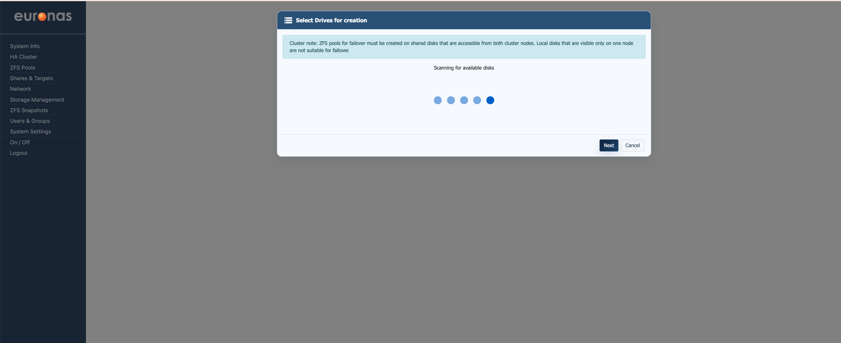
After selecting "Create New ZFS Pool" the system will begin scanning for available storage devices that are visible across the cluster. During this stage euroNAS validates disk visibility and confirms that the required shared storage is accessible before allowing pool creation to continue. Depending on the storage platform and number of connected devices this process may take several seconds to complete. Once the scan has finished the available disks will be presented for pool configuration.
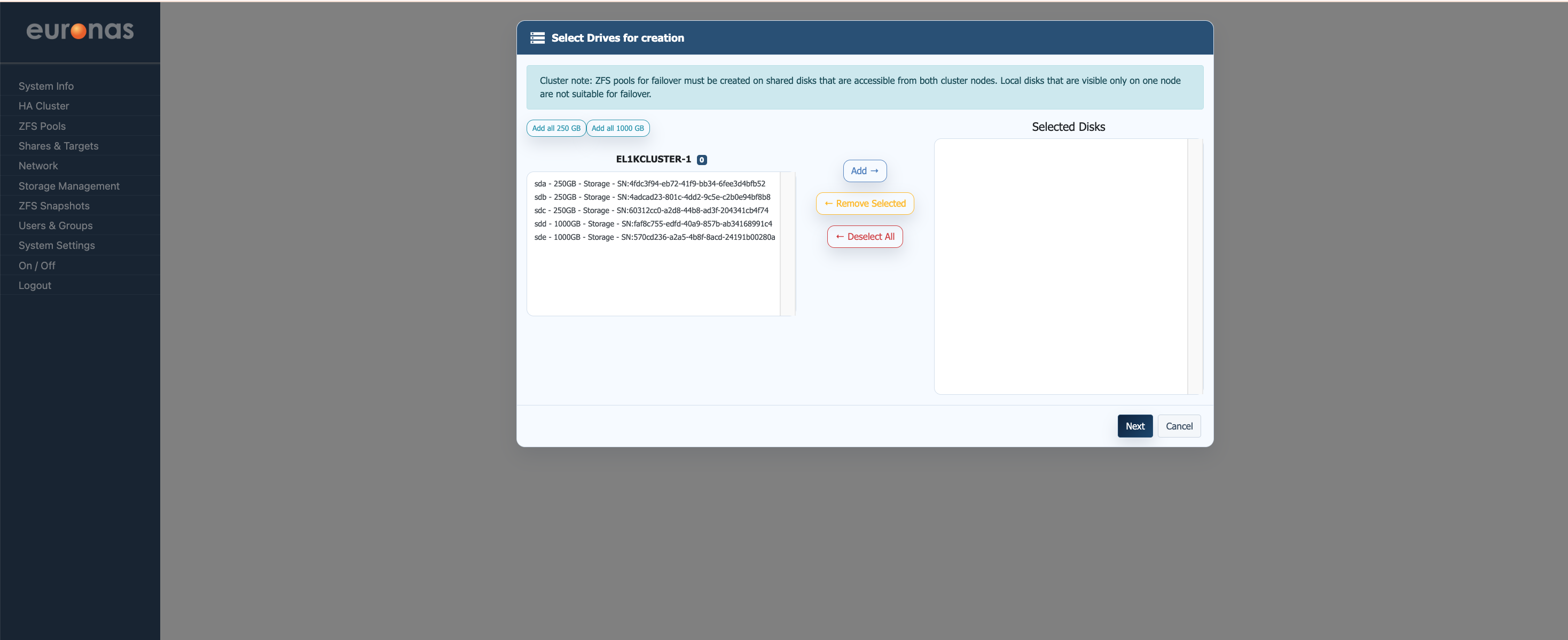
Once the storage scan has completed all available shared disks will be displayed. From this page the required disks can be selected and added to the pool creation process.
Each entry displays the device identifier, capacity, and associated storage serial information to assist with disk identification. Selected disks will appear in the Selected Disks panel ready for ZFS pool configuration.
The Add all options can be used to automatically select disks of a matching size, simplifying larger pool deployments where multiple identical disks are present.
For this example the 1 TB drives will be selected for pool creation. Once the required disks have been added to the Selected Disks panel, click Next to continue to the pool configuration stage.
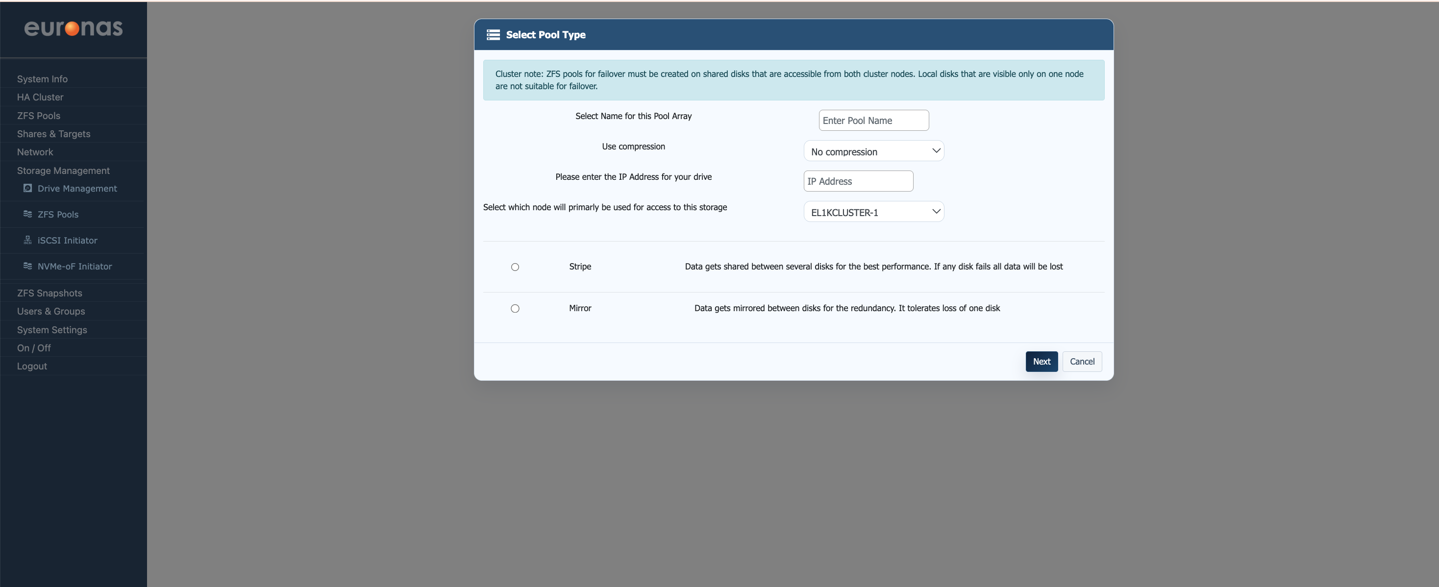
The Select Pool Type page is used to define the ZFS pool configuration and operating parameters. From this interface administrators can assign the pool name, configure compression settings, define the service IP address, and select the preferred active node for storage access.
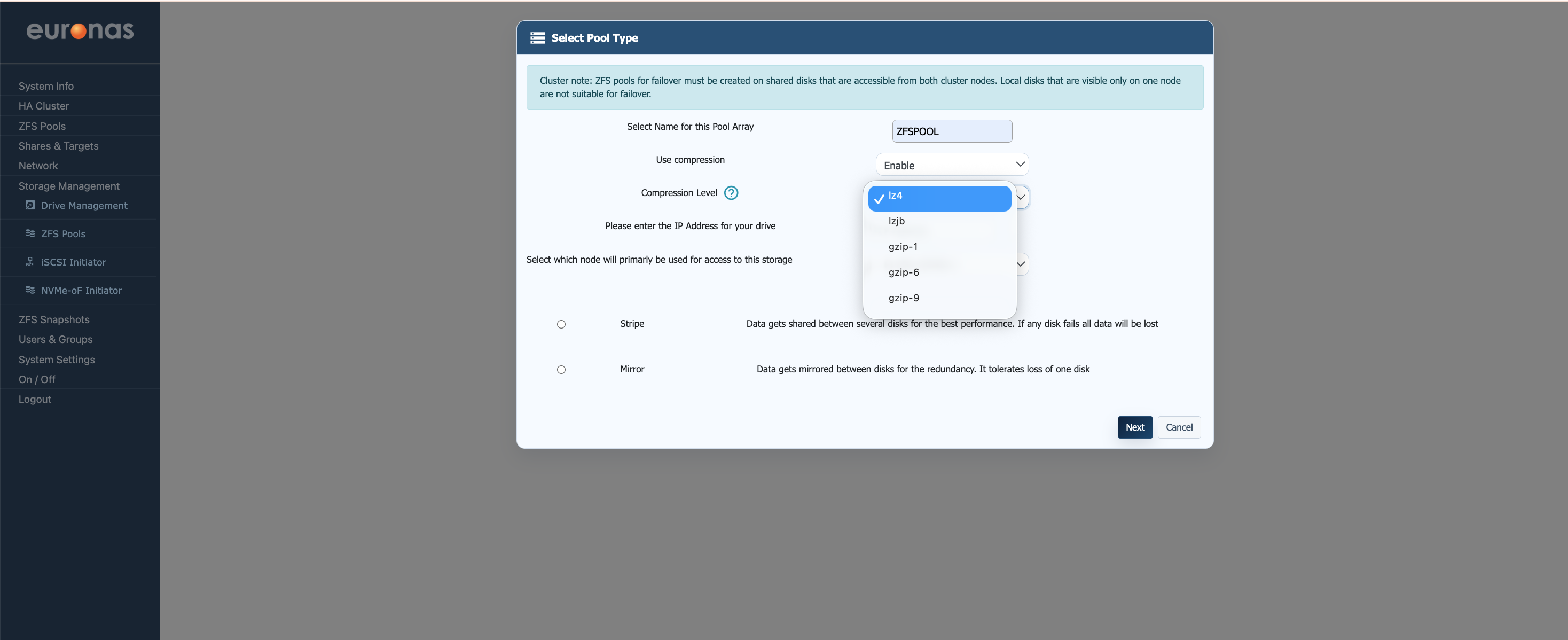
On the Select Pool Type page enter the required pool name and configure the desired storage options. Compression can be enabled or disabled depending on workload requirements, with multiple compression algorithms available including lz4, lzjb, and gzip levels. For most general-purpose workloads lz4 is recommended as it provides a good balance between performance and storage efficiency with minimal overhead. Higher compression levels may provide improved space savings but can increase CPU utilisation depending on the workload profile.
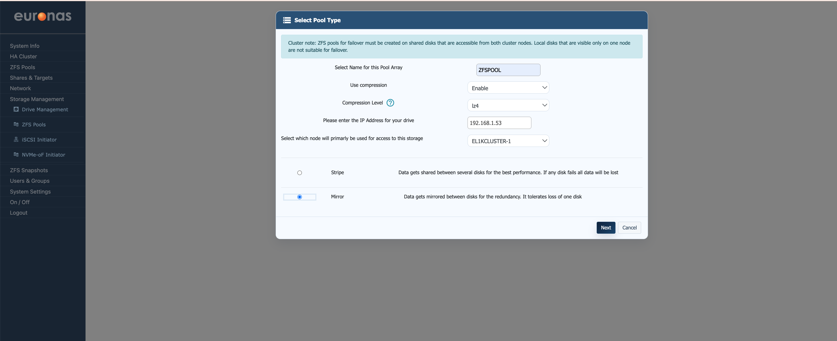
A floating service IP address must also be assigned to the storage pool. This address is used by the cluster to provide continuous storage access during node failover operations. The preferred active node for storage access can also be selected at this stage. For this example a mirrored pool configuration using two 1 TB disks has been selected to provide redundancy and resilience against single disk failure.
Once the required settings have been configured select Next to continue to the metadata configuration stage.
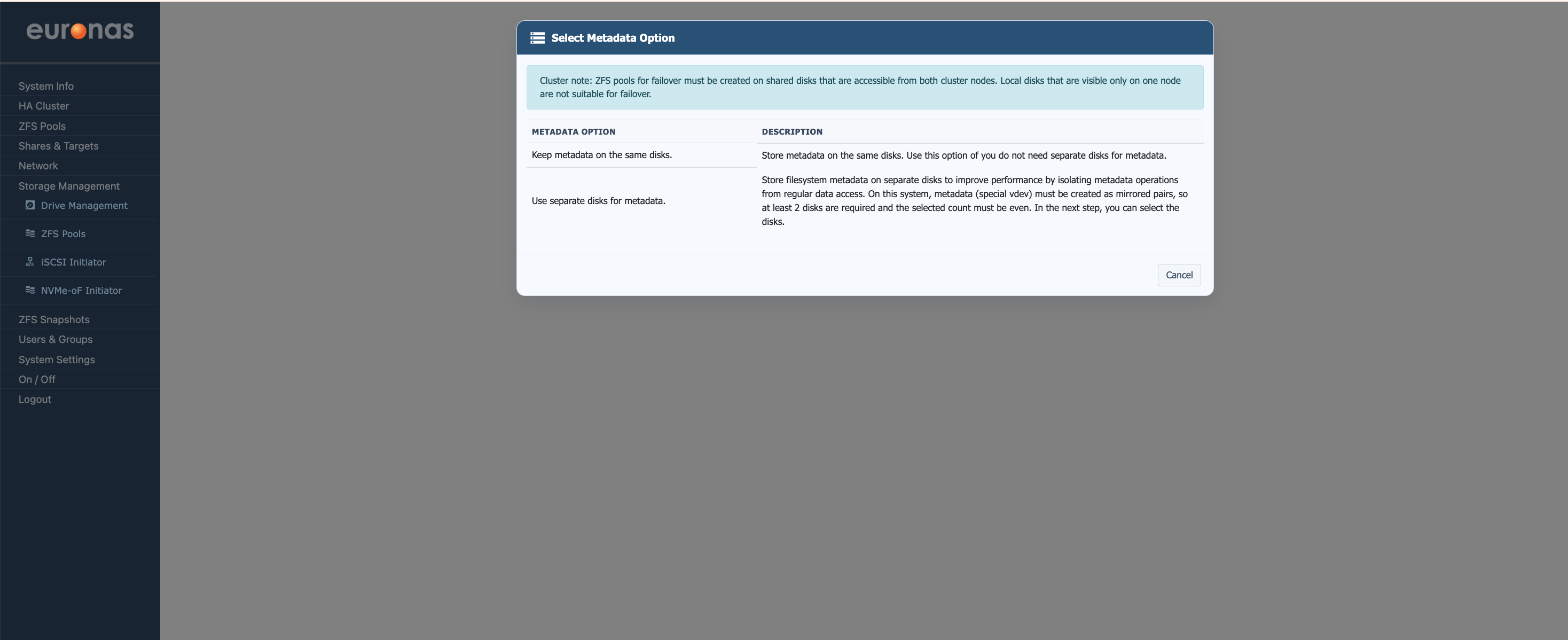
The Select Metadata Option page controls where filesystem metadata will be stored. Metadata can either remain on the main storage disks or be placed onto separate dedicated metadata devices to improve performance by isolating metadata operations from standard data access.
For smaller or general-purpose deployments metadata can remain on the primary storage disks. Larger or performance-sensitive environments may benefit from dedicated metadata devices, particularly for high IOPS or heavily virtualised workloads.
For this example separate dedicated metadata drives have been selected.
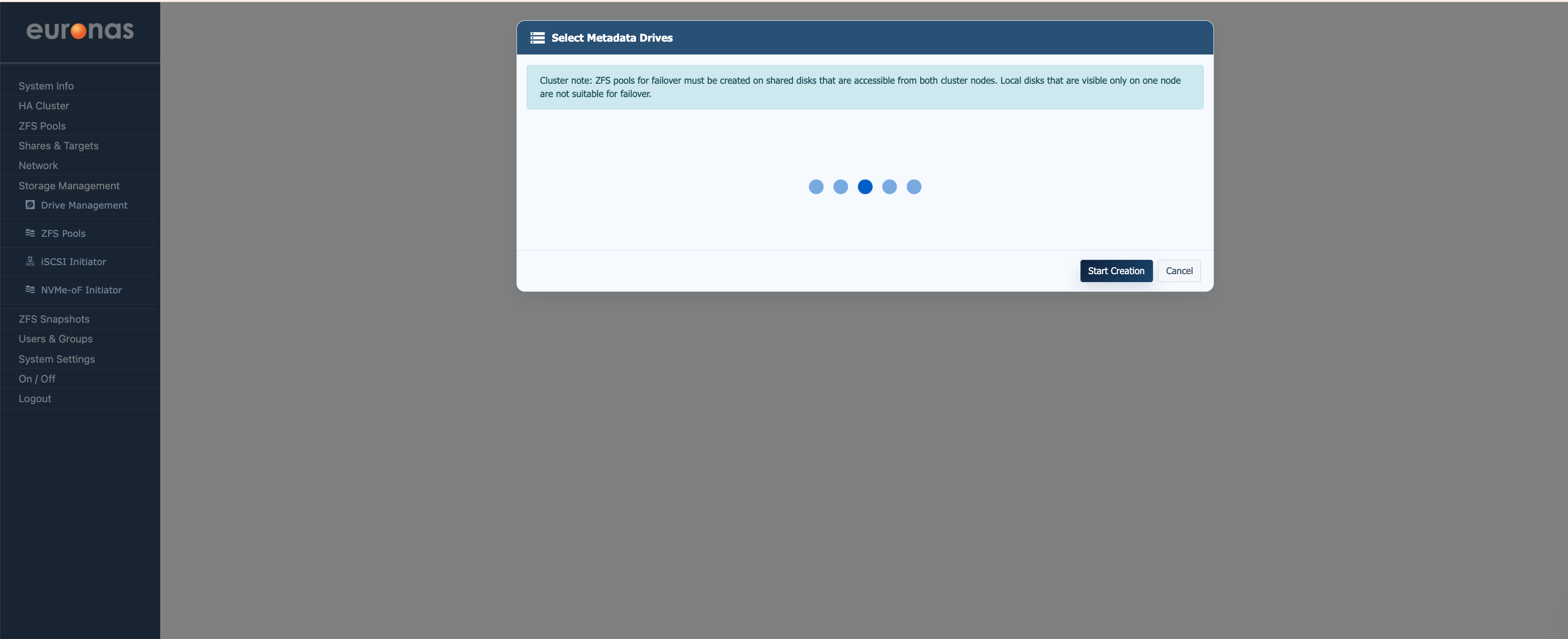
After selecting the dedicated metadata option the system will begin scanning for suitable metadata devices. Once the scan has completed all available metadata disks will be displayed for selection.
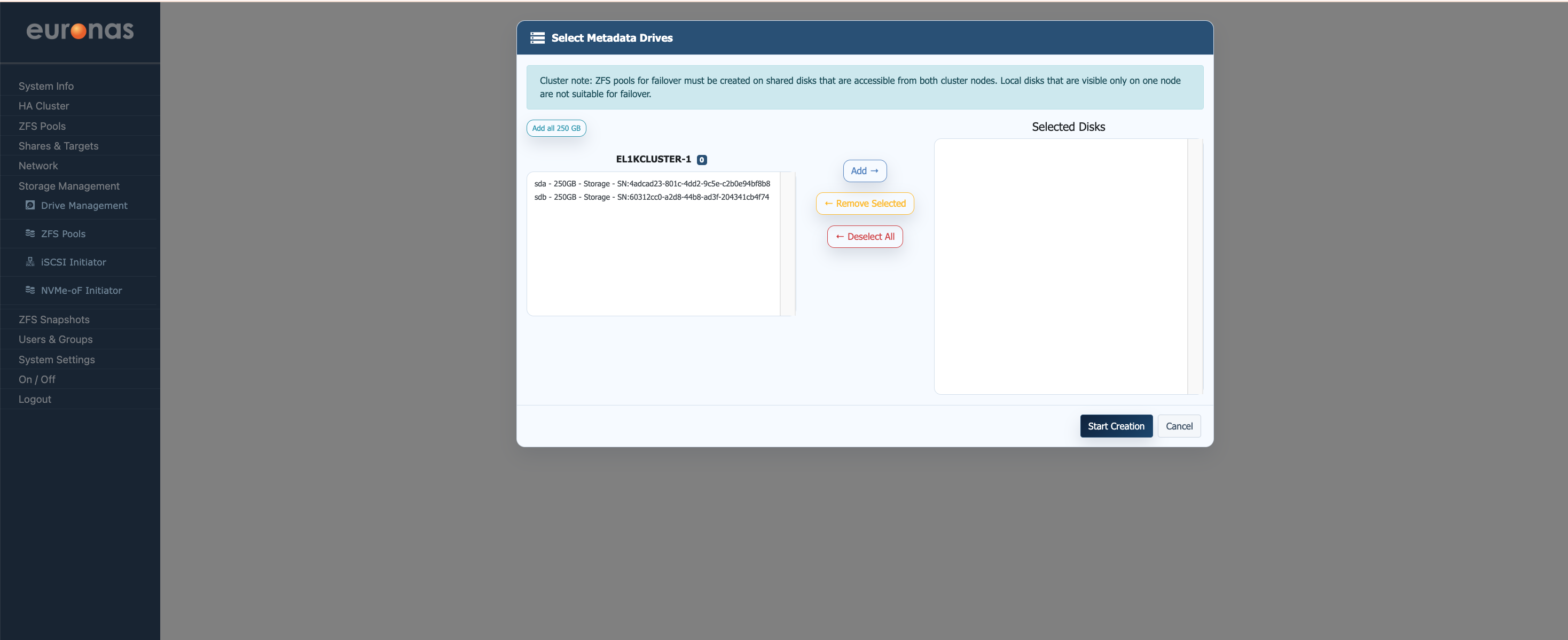
For this example two 250 GB drives have been selected to host the metadata layer. Metadata devices are configured as mirrored pairs to maintain redundancy and ensure metadata availability during disk failure scenarios.
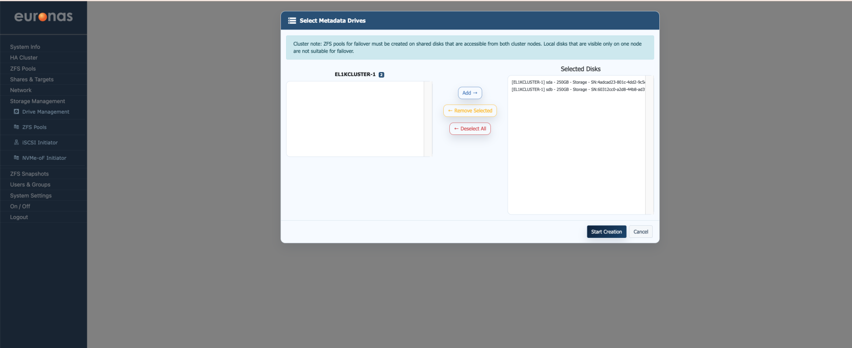
Once the required metadata disks have been added to the Selected Disks panel select Start Creation to begin the ZFS pool creation process.
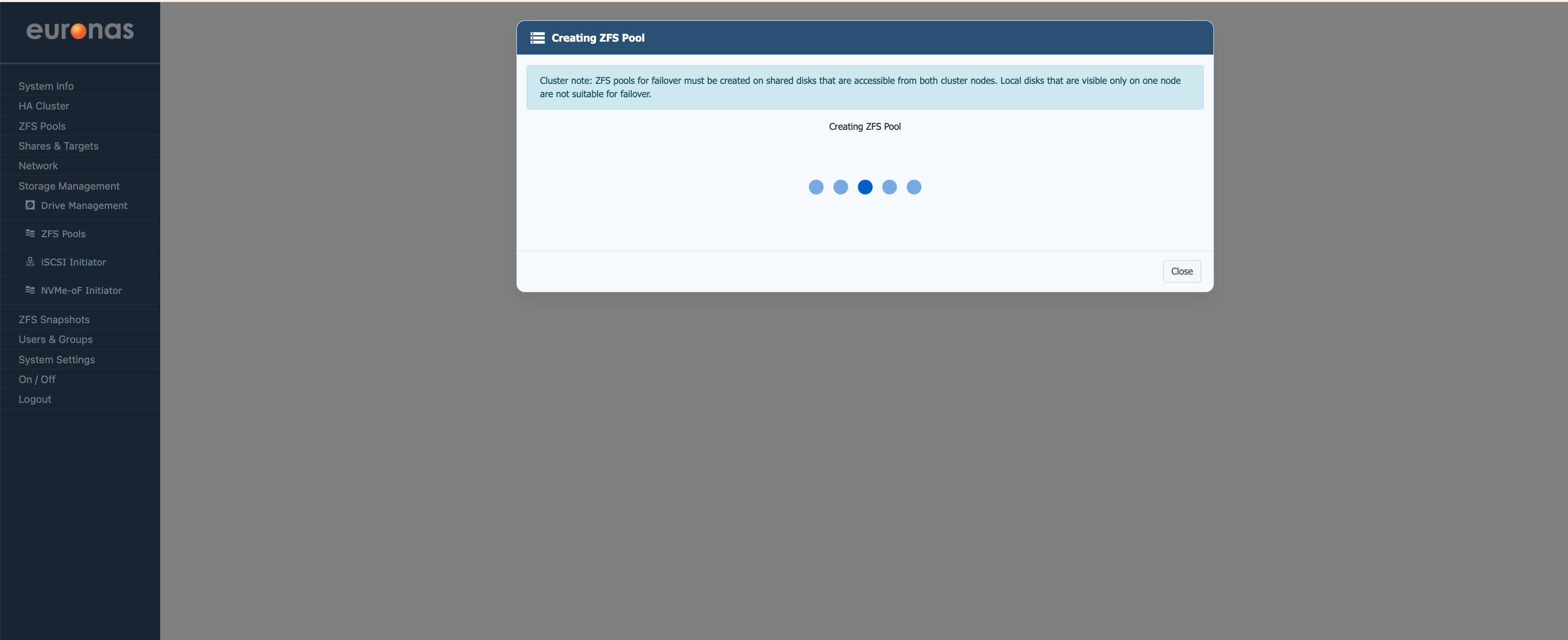
During this stage euroNAS will create the storage pool, configure the selected redundancy layout, initialise the metadata devices, and bring the filesystem online. Depending on the number of disks and storage performance this process may take several minutes to complete.
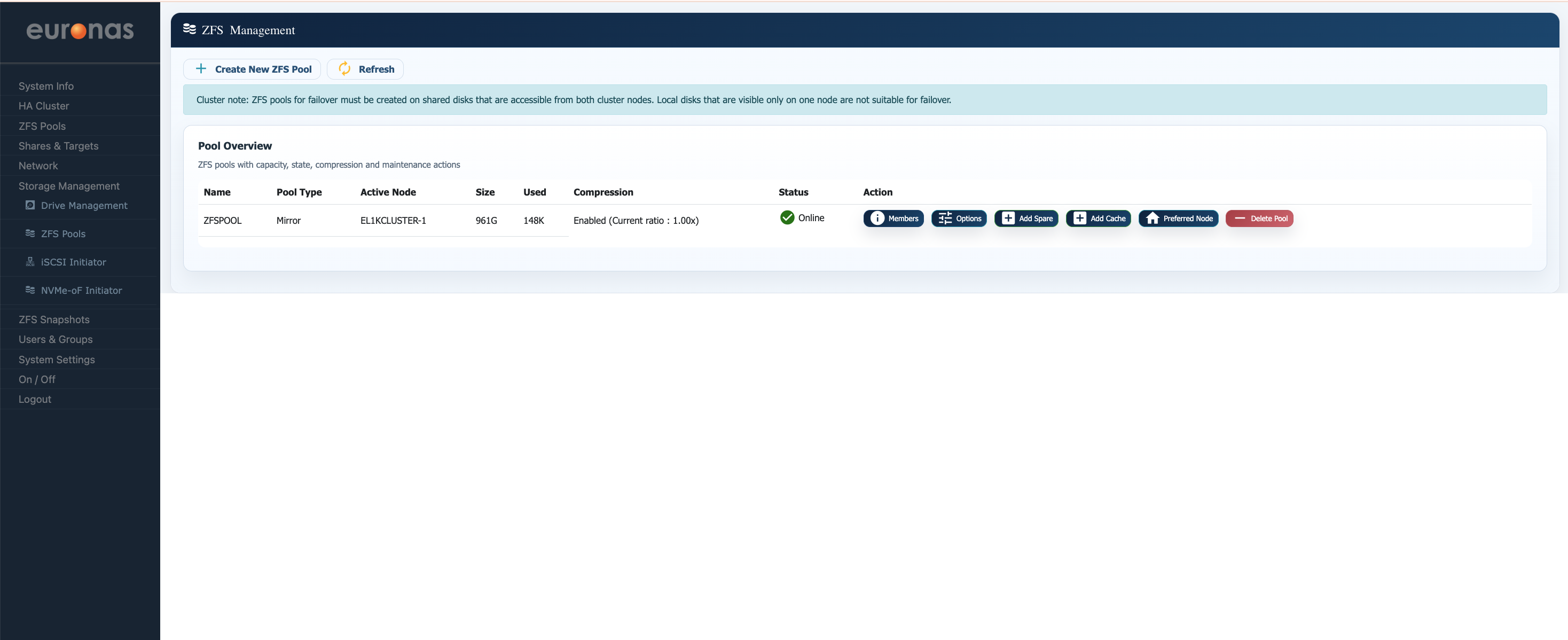
Once complete the newly created ZFS pool will appear within the Pool Overview section and will be available for shares, block storage, virtualisation workloads, and HA cluster services.